- 您现在的位置:买卖IC网 > Sheet目录370 > ZXLD1101ET5TA (Diodes Inc)IC LED DRVR WHITE BCKLGT SOT23-5
�� �
�
�Last� Time� Buy�
�Closest� Alternative� is� AP5724WUG-7�
�ZXLD1101�
�Inductor� selection�
�The� choice� of� inductor� will� depend� on� available� board�
�space� as� well� as� required� performance.� Small� value�
�inductors� have� the� advantage� of� smaller� physical� size�
�and� may� offer� lower� series� resistance� and� higher�
�saturation� current� compared� to� larger� values.� A�
�disadvantage� of� lower� inductor� values� is� that� they� result�
�in� higher� frequency� switching,� which� in� turn� causes�
�reduced� efficiency� due� to� switch� losses.� Higher� inductor�
�values� can� provide� better� performance� at� lower� supply�
�voltages.� However,� if� the� inductance� is� too� high,� the�
�output� power� will� be� limited� by� the� internal� oscillator,�
�which� will� prevent� the� coil� current� from� reaching� its�
�peak� value.� This� condition� will� arise� whenever� the� ramp�
�time� (I� LX(peak)� x� L/V� IN� )� exceeds� the� nominal� 5� s�
�maximum� 'on'� time� limit� for� the� LX� output.�
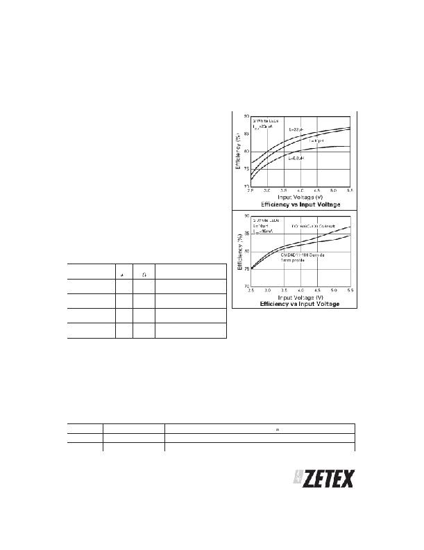
�The� graphs� opposite� show� the� ZXLD1101� performance�
�for� given� inductor� values� and� different� manufacturers.�
�Recommended� inductor� values� for� the� ZXLD1101� are�
�in� the� range� 6.8� H� to� 22� H.� The� inductor� should� be�
�mounted� as� close� to� the� device� as� possible� with� low�
�resistance� connections� to� the� LX� and� VIN� pins.�
�Suitable� coils� for� use� with� the� ZXLD1101� are� shown� in�
�the� table� below:�
�Part� No.�
�CMD4D11-100MC�
�L�
�(� H)�
�10�
�DCR�
�(� )�
�0.457�
�I� SAT�
�(A)�
�0.5�
�Manufacturer�
�Sumida�
�www.sumida.com�
�DO1608-103�
�10�
�0.16�
�1.1�
�Coilcraft�
�www.coilcraft.com�
�LQH31CN100�
�10�
�1.3�
�0.23�
�Murata�
�www.murata.com�
�LB2012Y100MR�
�10�
�0.5�
�0.1�
�Taiyo� Yuden�
�www.t-yuden.co�
�Diode� selection�
�The� rectifier� diode� (D1)� should� be� a� fast� low�
�capacitance� schottky� diode� with� low� reverse� leakage� at�
�the� working� voltage.� It� should� also� have� a� peak� current�
�rating� above� the� peak� coil� current� and� a� continuous�
�current� rating� higher� than� the� maximum� output� load�
�current.�
�The� table� below� gives� some� typical� characteristics� for�
�diodes� that� can� be� used� with� the� ZXLD1101:�
�Layout� considerations�
�PCB� tracks� should� be� kept� as� short� as� possible� to�
�minimise� ground� bounce,� and� the� ground� pin� of� the�
�device� should� be� soldered� directly� to� the� ground� plane.�
�It� is� particularly� important� to� mount� the� coil� and� the�
�input/output� capacitors� close� to� the� device� to� minimise�
�parasitic� resistance� and� inductance,� which� will�
�degrade� efficiency.� The� FB� pin� is� a� high� impedance�
�input� so� PCB� track� lengths� to� this� should� also� be� kept� as�
�short� as� possible� to� reduce� noise� pickup.� Excess�
�capacitance� from� the� FB� pin� to� ground� should� be�
�avoided.�
�Diode�
�ZHCS400�
�ZHCS500�
�V� F� @� 100mA� (mV)�
�300�
�300�
�I� FSM� (mA)�
�1000�
�1000�
�Ic� (mA)�
�400�
�500�
�I� R� at� 30V� (� A)�
�15�
�15�
�Package�
�SOD323�
�SOT23�
�ISSUE� 4� -� JULY� 2004�
�11�
�SEMICONDUCTORS�
�发布紧急采购,3分钟左右您将得到回复。
相关PDF资料
ZXLD1320DCATC
IC LED DRVR WHITE BCKLGT 14-TDFN
ZXLD1321DCATC
IC LED DRVR WHITE BCKLGT 14-TDFN
ZXLD1322DCCTC
IC LED DRIVR WHITE BCKLGT 14-DFN
ZXLD1350ET5TA
IC LED DRIVR WHITE BCKLGT TSOT-5
ZXLD1352ET5TA
IC LED DRIVER HIGH BRIGHT TSOT-5
ZXLD1356DACTC
IC LED DRIVER WHITE BCKLGT 6-DFN
ZXLD1360ET5TA
IC LED DRIVR WHITE BCKLGT TSOT-5
ZXLD1362ET5TA
IC LED DRIVR WHITE BCKLGT TSOT-5
相关代理商/技术参数
ZXLD1320
制造商:DIODES 制造商全称:Diodes Incorporated 功能描述:Buck mode DC-DC converter for LED driving
ZXLD1320DCATC
功能描述:直流/直流开关转换器 DC-DC Buck Conv. 1.5A output RoHS:否 制造商:STMicroelectronics 最大输入电压:4.5 V 开关频率:1.5 MHz 输出电压:4.6 V 输出电流:250 mA 输出端数量:2 最大工作温度:+ 85 C 安装风格:SMD/SMT
ZXLD1321
制造商:ZETEX 制造商全称:ZETEX 功能描述:Boost mode DC-DC converter for LED driving with 1A output and current control
ZXLD1321DCATC
功能描述:直流/直流开关转换器 DC-DC Boost Conv 1A output RoHS:否 制造商:STMicroelectronics 最大输入电压:4.5 V 开关频率:1.5 MHz 输出电压:4.6 V 输出电流:250 mA 输出端数量:2 最大工作温度:+ 85 C 安装风格:SMD/SMT
ZXLD1322
制造商:DIODES 制造商全称:Diodes Incorporated 功能描述:BUCK/BOOST MODE DC-DC CONVERTER
ZXLD1322DCCTC
功能描述:直流/直流开关转换器 Buck-Boost DC-DC Con 0.7A output RoHS:否 制造商:STMicroelectronics 最大输入电压:4.5 V 开关频率:1.5 MHz 输出电压:4.6 V 输出电流:250 mA 输出端数量:2 最大工作温度:+ 85 C 安装风格:SMD/SMT
ZXLD1322DCCTC-CUT TAPE
制造商:DIODES 功能描述:ZXLD1322 Series 15 V 600 kHz 700 mA Buck/Boost Mode DC-DC Converter - DFN-14
ZXLD1322DCTC
制造商:ZETEX 制造商全称:ZETEX 功能描述:Buck/boost mode DC-DC converter for LED driving with 700mA output and current control